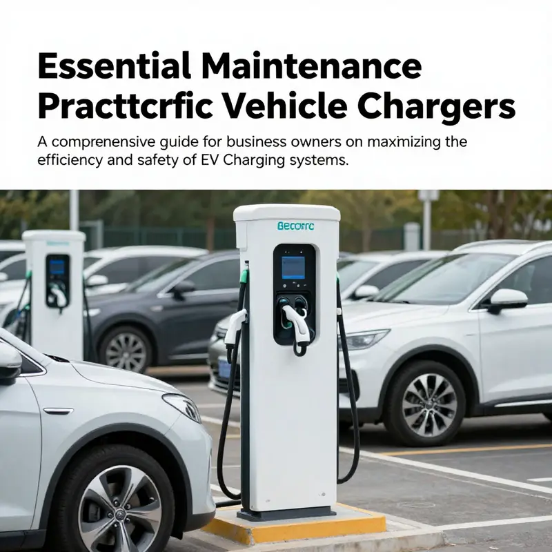
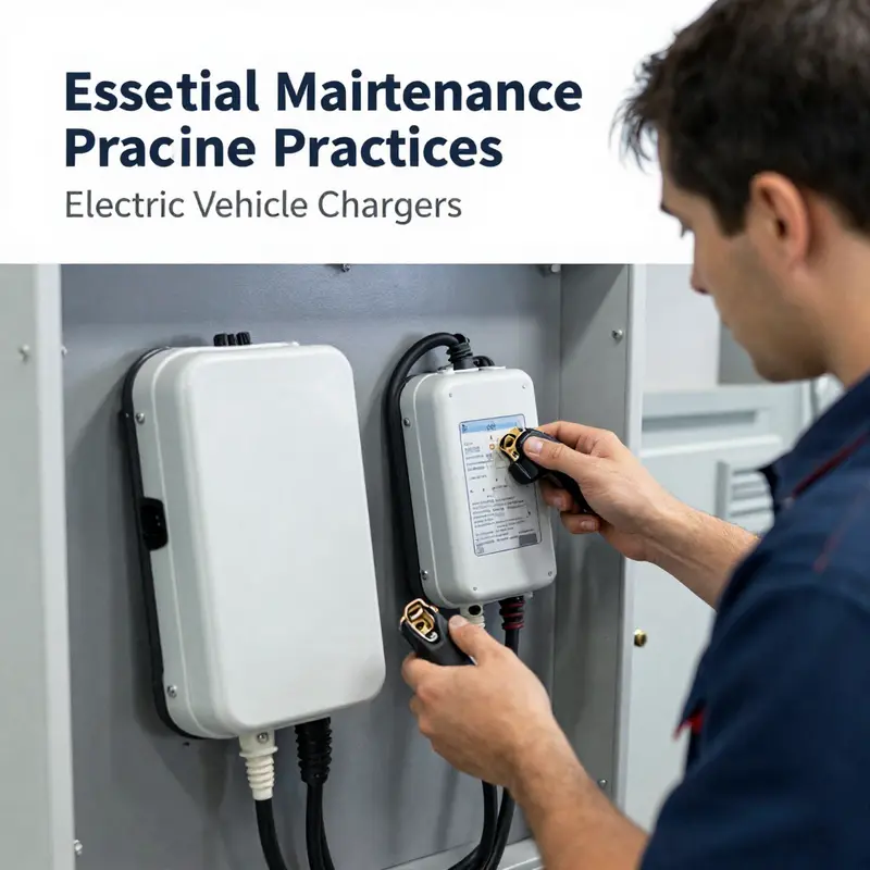
As electric vehicles (EVs) continue to grow in popularity, ensuring the optimal performance of electric vehicle chargers is paramount for businesses. Regular maintenance of these chargers not only enhances their efficiency but also guarantees safety and longevity. This guide outlines crucial maintenance practices that focus on cleaning and dust management, environmental sealing, inspecting components, verifying replacements, and troubleshooting common issues. By understanding and implementing these practices, business owners can foster a reliable charging experience for their customers while minimizing operational challenges.
Dust, Cooling, and Quiet Duty: The Essential Cleaning Rhythm for EV Chargers
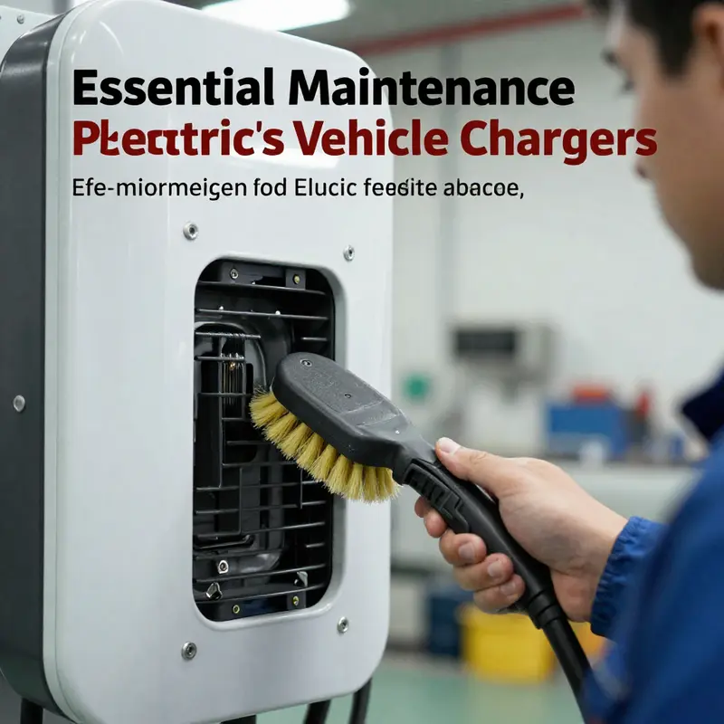
EV chargers sit at the edge of the electrical system, quietly ferrying kilowatts from the grid to a vehicle battery. They look simple, but behind the ports lies a compact, intricate ecosystem that works under constant stress. Regular cleaning and dust management are essential to keep cooling paths clear and seals effective.
Heat management is the core reason dust matters. Dust on fins and around fan blades acts like a blanket, reducing air movement and pushing temperatures higher during peak charging sessions or hot weather. Over time, thermal stress accelerates wear, reduces efficiency, and can trigger protective shutdowns that interrupt a charging session.
Dust invites electrical faults. Particles can settle in vents and gaps, degrade insulation, cause arcing, or disturb sensor readings. Because chargers sit at the interface of power and control signals, contamination can disrupt communication and safety.
Practical cleaning starts with a repeatable rhythm. Use low-pressure compressed air to loosen dust from exterior surfaces and vents, followed by a soft-bristled brush for louvers and seams. Wipe with a soft, dry cloth. Avoid moisture; water or liquids should be a last resort and applied sparingly if unavoidable. Short, frequent sessions beat long, infrequent scrubs.
Connector care matters. Inspect cables and plugs for cracks, fraying, corrosion, or burn marks. Replace worn parts promptly. Clean connections to reduce arcing and intermittent charging faults that can escalate.
Protection against environmental ingress is important. Outdoor units benefit from sealed enclosures and gaskets; IP-rated models help resist moisture and dust. Use dust filters and ensure seals remain intact after cleaning. Periodically replace filters as needed.
Maintenance cadence and documentation help. Keep a simple log: date, area cleaned, observed wear on cables, and the environment. In dusty settings, increase frequency of inspections and wipe-downs.
Component replacement: compatibility matters. When replacing parts, use OEM or certified parts that preserve electrical interfaces and communication protocols. Cleanliness helps prevent issues from mismatches that could lead to heat or miscommunication.
Together, cleaning flows into a broader preventive maintenance philosophy: it reduces mid-charge faults, extends service life, and improves safety. Follow the manufacturer’s guidelines for cleaning products and tools, and document the process to support reliability.
To connect this practice with wider vehicle care, view cleaning as protecting a complex system through routine, attentive care. If you want a quick reminder, keep it simple: clean, inspect, replace in time, and document. For deeper grounding, supplemental resources discuss how contaminants influence sensor readings, cooling efficiency, and system resilience. Example references exist in industry literature; consult model-specific manuals and standards to tailor the program to your installation.
Sealing for Safety: Environmental Protection in EV Charger Enclosures
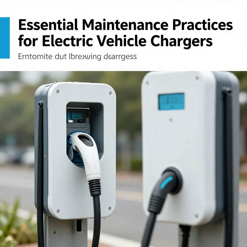
Electric vehicle chargers operate at the intersection of high-voltage power electronics and outdoor or semi-enclosed environments. The protective envelope around the charging interface must keep moisture, dust, salt spray, and UV radiation out of sensitive joints, connectors, and electronics. A failed seal is not just an inconvenience; it can enable short circuits, corrosion, and degraded performance that threatens safety and reliability over the charger’s life. Therefore, sealing is a foundational design consideration rather than a last-step afterthought.
A robust sealing strategy uses a layered approach. The outer enclosure is engineered to withstand weather exposure, with attention to ingress protection ratings, surface finishes, and gasket-mailure modes. The interface seams, cable-entry points, and charging gun housing are treated as multi-barrier zones where seals form primary, secondary, and tertiary barriers against water and dust, while accommodating vibration and thermal cycling.
Materials choices drive long-term performance. Liquid Silicone Rubber (LSR) gaskets are widely used around critical connectors for their wide temperature range, chemical resistance, and resilience to repeated heating and cooling. LSR formulations can maintain elasticity across typical automotive temperatures, from extreme heat to subfreezing nights. Proper selection also considers UV stability, as direct sun exposure can embrittle many elastomers; high-grade LSR compounds retain a large fraction of their tensile strength after extended UV exposure, translating to fewer replacements and lower maintenance costs. The geometry of the seal matters too: multi-lip profiles, dust shields, and precisely mated surfaces reduce capillary wicking and improve leak resistance.
Beyond gaskets, potting and encapsulation of internal connections are important. Single-component, fast-curing silicone-based potting compounds can protect sensitive electronics at cable entry points while maintaining elastomeric properties needed to tolerate movement and thermal expansion. These materials should bond to plastics and metals, preserve electrical insulation, and exhibit low volatile organic content to minimize outgassing and leakage risks. Proper curing and fill heights reduce voids that could harbor moisture.
Validation and maintenance complete the sealing lifecycle. Environmental aging, temperature cycling, and vibration are simulated in accelerated tests to verify long-term performance. Regular field inspections—checking for cracking, discoloration, or deformation of gaskets—help detect aging seals before failure. Leak testing, including helium mass spectrometry or pressure decay methods, can provide quantitative measures of seal integrity. In practice, maintaining an accurate log of seal replacements, installation dates, and exposure conditions supports proactive maintenance planning and reduces unexpected downtime.
Installation considerations are also critical. Not all chargers reside in perfect weatherproof enclaves; some operate in semi-exposed locations with wind-driven rain, road spray, or salt-laden air. Sealing strategies must account for installation geometry, mating surface finishes, lubricants, and the compatibility of sealants with chosen plastics and metals. IP65 or higher ratings are commonly targeted for charging interfaces, but achieving these ratings requires coordinated design across enclosure geometry, gaskets, cable glands, and enclosure-to-door interfaces.
Economics and lifecycle implications matter. Mismatched seal materials or incompatible components can create new failure modes that undermine the intended protection. Keeping a bill of materials, supplier certifications, and maintenance records helps ensure compatibility and traceability. In-field replacements should use approved, standards-compliant seals and adhesives rather than improvised substitutions. A well-managed sealing program contributes to longer service intervals, reduced fault rates, and safer, more reliable charging for end users.
Ultimately, sealing is about safeguarding the core function of the charger: delivering safe, reliable power under a wide range of environmental conditions. A disciplined approach to material selection, geometric design, validation, and maintenance allows the charging system to resist moisture and dust ingress while maintaining thermal performance and electrical integrity. When done well, seals extend component life, reduce maintenance burden, and give technicians and customers confidence that the charger will perform when called upon, come rain or shine.
null
null
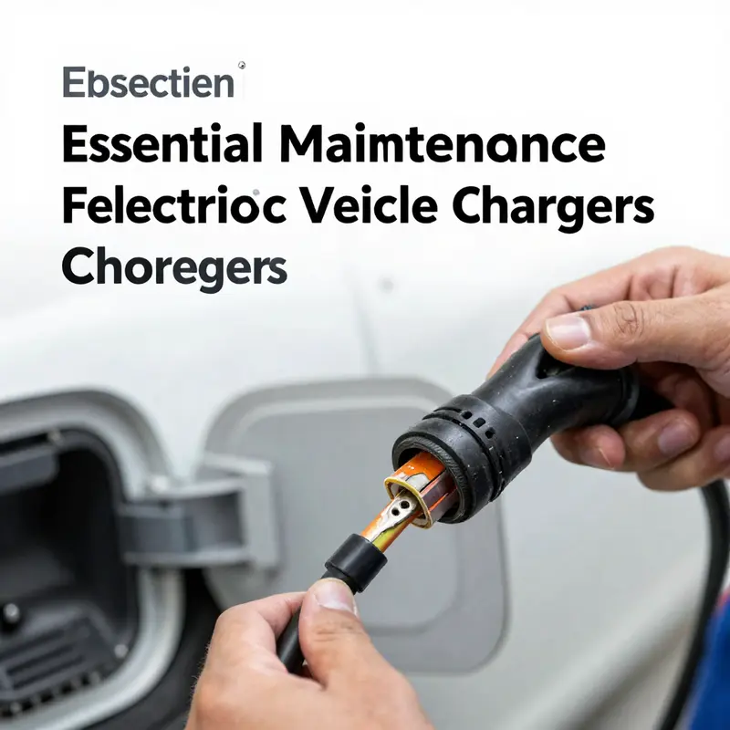
Guarding the Charge: Verifying Compatibility When Replacing Electric Vehicle Chargers
Replacing an EV charger is more than a swap of hardware. It is a careful alignment of standards, interfaces, and software that keeps the vehicle’s energy system safe and efficient. When an owner or technician considers a replacement, the aim should be to preserve, or ideally improve, the integrity of the charging path from the wall to the battery. The risk of careless substitution is not merely a charging hiccup; it can compromise the battery management system, undermine safety protections, or trigger heat buildup that shortening the life of the onboard charger. The process begins long before any plug is connected. It starts with a precise understanding of what the vehicle expects and what the replacement charger can deliver. The fundamentals are straightforward in concept but demanding in execution: confirm the charging standard, match the physical interface, verify electrical specifications, and ensure the communication protocols can negotiate charging parameters reliably. All of this rests on a foundation of careful documentation, methodical testing, and adherence to established safety guidelines that govern electrical systems in mobile environments. This is not about chasing the latest efficiency claim or chasing a higher kilowatt rating for its own sake. It is about ensuring compatibility so that the charging system, the vehicle, and the power source speak the same language at every step of the process.
The first question is the charging standard. In many markets, the vehicle’s charging standard is the most fundamental determinant of compatibility. GB/T remains dominant in certain regions, while CCS has become the de facto multi-standard solution across Europe and North America, and CHAdeMO represents a legacy approach found in older models. The correct standard is not merely a matter of plug shape; it defines the protocol, safety checks, and negotiation that happen as soon as the plug is engaged. To identify the standard, one consults the vehicle’s user manual or the manufacturer’s official resources, often using the VIN as a key. This verification is essential because a charger built for one standard physically cannot connect to a different one without specialized adapters that are rarely recommended for regular use. When standards are aligned, the handshake can occur smoothly, allowing the vehicle to negotiate charging rates, voltage, and timing with the charger. When they are not, no amount of wiring magic will salvage a stubborn, non-communicating connection. The moment of truth arrives with the electrical and electrical-communication marriage of the two devices. The classic mistake is assuming that a compatible plug equals a compatible charging experience. A charger may fit, but if the standard mismatch has not been resolved, the system will stall before any current flows, and the driver will be faced with a perplexing failure.
Even when the standard matches, the physical interface must be spot-on. The connector type is the visible face of compatibility, but it is only the beginning. A CCS connector will not slot into a GB/T vehicle, and the reverse is true as well. The shape, the pin configuration, and even the resilience of the connector under repeated mating cycles matter. A replacement unit may have the correct electrical output on paper, but if the physical geometry is off or the pins do not align correctly, there is no connection worth speaking of. This is why a meticulous comparison of the current and replacement hardware is essential. Observers should measure, or at least verify, the connector family, the current rating of each contact, and any alignment features that assure a secure, weather-tight fit. The risk of a loose or misaligned contact goes beyond a simple charging delay; it can generate arcing, heat, and accelerated wear of both the plug and the vehicle port. The safety implications alone argue for a careful, standards-driven approach that prevents nonconforming parts from entering the system.
Beyond physical fit, the electrical specifications demand scrupulous matching. The voltage level must match the vehicle supply needs, whether it be the AC wall supply of roughly 230 volts or the higher-spec DC fast charging range that can push hundreds of volts through dedicated HV lines. The current rating is equally critical. A charger that can supply more current than the vehicle can safely accept is not dangerous in itself, but it yields diminishing returns and can still stress the wiring and connectors. Conversely, a charger that cannot supply enough current will limit charging speed, frustrate users, and potentially cause the onboard charger to operate near its upper limits for prolonged periods. The power output must be compatible with the onboard charger’s capacity. A mismatch—too little power from the charger or, less commonly, a charger that tries to push a higher power level than the car’s hardware can safely handle—can trigger protective measures within the BMS or charging control logic. In either case, the result is suboptimal charging behavior that undermines the purpose of the upgrade.
The matter of communication protocols is the invisible but crucial layer that connects all the hardware. Modern charging systems negotiate parameters using standardized digital communication. Protocols such as ISO 15118 and GB/T 27930 govern how the charger and vehicle exchange information about state-of-charge, authentication, charging rates, and safety limits. A physically compatible charger may still fail to initiate charging if the handshake cannot be established. This is not a fault of the hardware but a failure of interoperability. Therefore, professional testing becomes essential. Independent verification labs and certified installers often run a suite of compatibility tests that validate both control circuitry and protocol timing. The tests confirm that the charger and vehicle can exchange the necessary data reliably and without error, and that the system can gracefully handle fault conditions. In practice, this means confirming that the control logic, error handling, and fallbacks are aligned with international standards like IEC 61851 and ISO 15118, as well as national regulations. The outcome is not simply whether charging begins; it is whether the entire process remains safe, predictable, and resilient under typical operating conditions and potential fault scenarios.
To navigate this complex terrain, a disciplined set of steps guides the replacement project. The process begins with gathering official documentation from the vehicle and the charger. The VIN, the vehicle’s user manual, and the original charging interface documentation should be cross-checked to confirm the exact standard, connector type, voltage, and current limits. Only after these checks should a replacement be sourced. The next phase focuses on physical compatibility: the connector geometry, the pin configuration, and the mating tolerances must be verified. If the replacement looks the same on the outside but encodes a different communication protocol inside, the result will be a stubborn nonstarter. The electrical checks follow, ensuring that voltage, current, and power ratings align with the vehicle’s onboard charger. Where possible, the replacement should be tested at low power first to confirm that connection is stable and that the control handshake proceeds without error. The observation of heat buildup is a critical indicator; a newly connected system should not produce excessive temperatures at contact points or connectors during initial operation. The testing sequence should include a diagnostic scan of the vehicle’s charging subsystem, inspection of cable insulation, and a check for any unusual sounds or smells, all of which can signal underlying incompatibilities.
In parallel with the technical checks, environmental and safety considerations deserve equal attention. If the charger being installed is not sealed or rated for automotive environments, moisture ingress and dust can undermine long-term reliability. The use of sealed, IP-rated enclosures reduces these risks and protects critical components from the elements. A clean, dry installation space reduces the chance of corrosion on connectors and ensures stable electrical contact. The safety implications extend to the surrounding electrical installation as well. Regular maintenance literature emphasizes the vulnerability of outdoor or unprotected connectors to humidity, temperature cycling, and contaminants that can migrate into contact areas. The preventive logic is straightforward: well-sealed hardware paired with thoughtful enclosure design survives harsher conditions and provides a longer service life. This is not merely a matter of comfort or convenience; it directly affects safety and reliability over the life of the vehicle and its charging system.
The practical upshot of careful compatibility verification is clear. When done right, an replacement charger preserves the integrity of the vehicle’s battery management system, keeps safety protections intact, and ensures charging performance that aligns with the original design intent. The process also minimizes the risk of unforeseen interactions with other vehicle subsystems, such as thermal management or power electronics, that could be stressed by a mismatch. As a practical reminder, maintenance-minded readers may wish to consult manufacturer guidelines and rely on OEM or certified replacement parts. For broader context on vehicle upkeep and maintenance philosophy, see what is vehicle maintenance. Above all, the replacement should be treated as a systems integration task rather than a simple hardware swap. A meticulous approach—documented standards, verified physical fit, aligned electrical specs, and confirmed communication—the only recipe that yields dependable, safe, and efficient charging after a replacement.
Finally, for those who want to explore the formal grounding of these standards, reference materials such as the IEC 61851-1 Standard provide the authoritative framework for charging system behavior, safety, and interoperability. External resources can deepen understanding and support a rigorous installation approach. External standard reference: https://www.iec.ch/standard/61851-1.html
Diagnosing and Resolving Common EV Charger Anomalies: A Practical Path to Reliable, Safe Charging
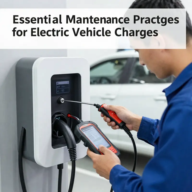
Charging is the quiet workhorse of electric mobility. When a car pulls into a stall, the charger should respond with predictable behavior, delivering power in a controlled, monitored process. Yet, like any electrical system, EV charging can present a spectrum of anomalies. This chapter treats troubleshooting as a disciplined maintenance practice rather than a panic response. It emphasizes calm diagnosis, safety, and a preference for parts and procedures that align with manufacturer recommendations. In practice, most charging faults originate outside the onboard charger itself—dust in a port, a loose connection, or a temporary software hiccup—yet a methodical approach to diagnosis helps you separate symptoms from root causes and prevents unnecessary component replacement. The objective is to restore reliable behavior while preserving the long-term health of the vehicle’s charging interface and the broader electrical system it relies on.
One of the most frequent issues is a failing charging connection, often described by the user as a “vehicle not recognized” message or a communication error. The causes sit on both sides of the contact: the physical interface and the electronic handshake. A poor physical connection is the simplest culprit. If the charging gun isn’t fully inserted or locked, or if the vehicle port has accumulated dust, moisture, or corrosion, contact quality deteriorates and the system fails to establish a stable dialogue. On the software side, a temporary fault in the vehicle’s onboard computer or the charger’s communication module can interrupt the handshake even when the hardware looks pristine. Finally, compatibility matters. Some older EVs do not support newer fast-charging protocols, and attempting to push a protocol the car does not understand will stall the exchange without necessarily indicating a broken charger. The remedy is straightforward and repeatable: re-seat the connector firmly until you hear a lock, inspect both the gun and the vehicle port for debris or moisture with a dry, lint-free cloth, and avoid liquids that could wick into sensitive contacts. If the problem persists, a quick system reset helps—cancel the current session, wait a moment, then restart the charging sequence. In parallel, a check of the vehicle’s charging settings can reveal a permission control that blocks charging when the car is locked. If the issue endures, try a different charger to confirm whether the fault lies with the vehicle or the station, and verify that the charging standard matches the car’s capabilities.
The next scenario—extremely slow charging—often tests patience more than it tests equipment. The root causes can be shared between the vehicle and the charger. The battery’s own thermal strategy is a frequent bottleneck. When the Battery Management System detects temperatures outside the safe range, it throttles charging to protect cells. A second common factor is the state of charge. As SoC climbs past roughly eighty percent, most chemistries automatically taper the current to minimize heat and preserve long-term health. If the charger and car are both healthy, external conditions like the power supply can set the pace. A power mismatch is a frequent culprit: a car that can only draw 60 kW is offered a 120 kW charger and ends up with a negotiation that yields far less than the adapter’s maximum, simply because the car won’t accept more. Wiring quality matters too. A low-quality extension cord or undersized wiring in a home circuit can cap the actual power delivered, even when the charger is capable of higher output. High-power accessories running during charging—such as cabin heating or climate control—can divert energy away from the battery, further reducing the charging rate. The practical response is multi-layered: confirm the car’s maximum charging rate and select a charger with matching or superior capability, pre-condition the battery in cold weather through the vehicle app to raise its temperature before connection, and avoid high-power usage during charging when possible. For those using cables, ensure the lead is rated for the required current and free from insulation damage, kinks, or wear. Finally, switch off energy-intensive accessories during charging to minimize parasitic draw and let the battery’s BMS do its job more efficiently.
Charging sessions can also stop unexpectedly, which tests both the reliability of the network and the robustness of the vehicle’s control logic. The typical causes here include grid instability, which can create momentary transients that trip safety protections; temporary communication failures that disrupt the handshake; thermal protection triggering because either the car or charger overheats; and, in rarer cases, internal hardware faults. The reassurance is that most interruptions are transient and resolvable with a few deliberate steps. Start by re-plugging the connector firmly; this often clears a momentary miscommunication and re-establishes a clean channel. If the interruption recurs, charge during periods of lower energy demand to reduce grid stress, and allow the system to cool for a while before attempting again. Testing with another charger helps isolate whether the fault is in the vehicle or the charging point. If failures persist, engage professional diagnostics—maintaining a network service channel or vehicle service center to run deeper checks on the onboard electronics, firmware, and communication subsystems.
Charger displays that show a fault or error demand careful attention. A standing fault could point to a failed charger module, a damaged port, or a software issue within the charging management stack. Environmental factors—extreme temperatures, humidity, or dust ingress—also contribute to sporadic malfunctions. The prudent response is to treat a fault as a signal to pause charging and initiate a staged investigation rather than a hasty replacement. Start by reporting the fault to the operator or the vehicle’s manufacturer portal, then inspect the vehicle port for visible signs of damage, melting, or burns. Do not attempt to repair port damage yourself; such actions risk further harm or personal injury. Software updates can resolve known bugs in the charging interface or the vehicle’s charging management software, so check for available updates and install them if possible. If the environment is unfriendly—intense heat, direct rain exposure, or high humidity—relocate the vehicle to a sheltered space when feasible. In this context, the maintenance philosophy is clear: fast fixes can be misleading. A structured approach that validates physical integrity, confirms software state, and respects environmental boundaries yields safer and longer-lasting charging behavior.
As these patterns show, underlying causes often trace back to issues that maintenance routines can address before they become failures. Regular cleaning and inspection remain foundational. Dust and moisture are the adversaries of contact quality, especially around external cooling fins, ports, and connectors. Non-sealed or poorly sealed chargers invite ingress that accelerates corrosion and short circuits. Where feasible, upgrading to sealed, IP-rated automotive-grade units reduces exposure to dust and water, effectively giving the charging stack a protective armor. Wear-and-tear components—such as the charging cable, the plug, connectors, and their insulation—should be checked routinely, not only for obvious cracks or discolouration but for soft spots, softened plastic, or loosened contacts that can escalate into arcing. Any sign of damage should trigger immediate replacement with OEM or certified parts to preserve compatibility and safety.
Compatibility is another pillar of reliable maintenance. When it is time to replace a charger or its connectors, ensuring that interfaces—including pins, cables, and communication protocols—are compatible is essential. Mismatches can introduce poor contacts, heat buildup, and even damage to the battery management system. The safest course is to source parts from the vehicle manufacturer or certified partners and verify protocol support before installation. This approach minimizes intermittent charging or sudden shutdowns caused by protocol negotiation failures.
Diagnosing problems often reveals that many symptoms are external in origin. A sticky or dirty port, a loose connection, or a temporary software hiccup can masquerade as a hardware fault. The guidance echoed through professional standards is to verify external factors first, then move inward toward the charger’s internal modules if needed. This sequence reduces unnecessary replacement, saves downtime, and preserves safety margins. A practical mindset for users and technicians alike is to approach each fault with a calm triage: confirm the simplest physical cause, re-seat and clean interfaces, restart the system to clear transient faults, and then verify system compatibility and settings before escalating. In more persistent cases, a broader diagnostic run using diagnostic tools and manufacturer software becomes appropriate, always with safety as the guiding principle.
For readers seeking deeper technical insight into charging troubleshooting, a focused resource on battery charging troubleshooting tips can provide extended practical scenarios and diagnostic logic. See the article aux-switches-temporarily-unavailable-battery-charging-troubleshooting-tips for a complementary perspective on power management nuances during troubleshooting.
Ultimately, the aim of troubleshooting within the broader maintenance framework is straightforward: keep the charging loop clean, sealed, connected, and well-mated to the vehicle’s charging system. Regular attention to the ports, connectors, and cables, combined with cautious software checks and adherence to OEM guidelines, yields the most reliable outcomes. When in doubt, moving through the steps in sequence—clean, reseat, reset, verify, and replace with certified parts—reduces risk and supports long-term performance. This disciplined approach aligns with the broader maintenance narrative that a well-kept charger underpins safety, reliability, and efficiency in everyday EV use.
External reference: https://ieeexplore.ieee.org/document/10583762
Final thoughts
Maintaining electric vehicle chargers is essential for ensuring operational efficiency and safety for businesses that cater to EV users. Regular cleaning, proper sealing, inspection of components, verification of replacements, and effective troubleshooting play significant roles in the longevity and reliability of charging systems. By adhering to these best practices, business owners can enhance customer satisfaction and minimize downtime, paving the way for a successful venture in the evolving electric vehicle landscape.